Here is a short animation that I put together to show what happens in Gimbal Lock. If the Y (Green) rotation axis is rotated so that the X (Red) and the Z (Blue) axes are lined up, there is no way to rotate across the imaginary rotation axis (Yellow) from the down position of the arrow to pointing up. What happens instead is a winding path upwards as the 3 axes move simultaneously to correct the position. This can happen if any 2 axes line up.
There are some great video explanations for this on GuerrillaCG.org, you'll most likely notice that is where I got the inspiration behind my animation. It's a two-part video tutorial on how Gimbal Lock can cause some rotation issues.
The Rotation Problem
Euler Rotations Explained
Check 'em out!
-Cliff
Tuesday, May 25, 2010
Wednesday, May 19, 2010
Face Patch Modeling 1
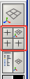
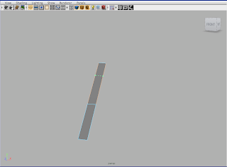
Start off in the side view with the 4-view button.
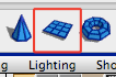
From the side view create a plane with the Polygon Plane button.
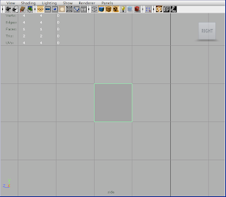
Right-click on the plane and switch to vertex mode to begin positioning the plane.
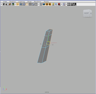
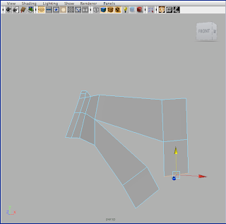
Position the vertices until you have a long narrow shape somewhat like the one in the image (don't be to worried about the shape now, it will become more defined as you get more geometry).
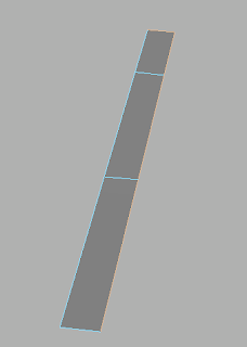
Using the Insert Edge Loop tool, insert two edge loops in the polygon.

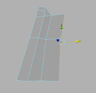
Right click on the mesh and switch to edge mode. Select the outer 4 edges on the right-hand side of the mesh and use the extrude tool to pull out new geometry.
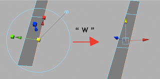
Switch to move with the "W" key and pull the geometry out.
Sculpt the vertices a little to shape the nose.
Next, select the two edges on the side of the nose and extrude these out.
Move these new vertices where you would like and then extrude each of the side edges individually. (If you have them both selected they will be connected, we don't want this).
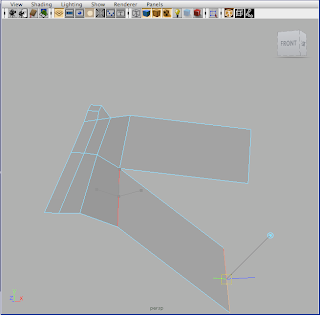
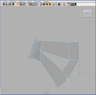
What we've created is the bridge of the nose and coming out from the side we have the upper and lower cheek. From here, sculpt your vertices and we'll create a polygon loop around the face.
Extrude two more sections from the ends of the upper and lower cheek geometry.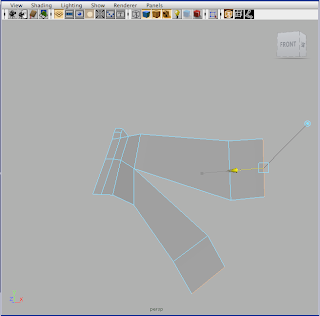
These will start our face loop, from the bottom of the top cheek extrusion extrude one more face to connect to the lower cheek.
Switch to vertex mode and select the bottom two vertices of this new face one at a time and using the move tool ("W") hold "V" to snap them to the vertex on the lower cheek extrusion.
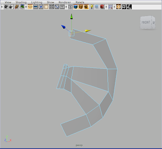
This is the beginning of the loop around the face, from here we are going to make one extrusion from the lower cheek to go around the mouth area, and two extrusions for the forehead.
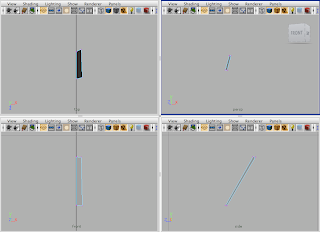
Now shape up the vertices, and lets take a look at 4-view to see how this should look from different angles.
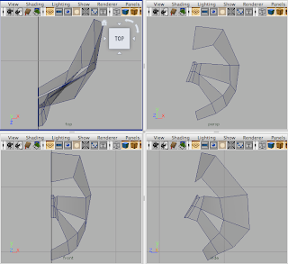
If you snap your vertices to the Y-Z plane then it will be easy to mirror the face after building half of it. To snap a vertex to a point on the grid, use one of the orthographic views (front/side/top) and using the move tool ("W") hold down the "X" button to snap to grid points. (You can click on only one direction with the move tool if you only want it to snap to the Y or Z axes.)
This sets up the face with good edge flow, a loop around the face for adding detail and slots for the eyes and the mouth. In the next face patch modeling tutorial I'll go over building the eyes sockets and mouth each with their own edge loops for adding detail without affecting the overall mesh.
- Cliff

From the side view create a plane with the Polygon Plane button.


Right-click on the plane and switch to vertex mode to begin positioning the plane.
Position the vertices until you have a long narrow shape somewhat like the one in the image (don't be to worried about the shape now, it will become more defined as you get more geometry).

Using the Insert Edge Loop tool, insert two edge loops in the polygon.


Right click on the mesh and switch to edge mode. Select the outer 4 edges on the right-hand side of the mesh and use the extrude tool to pull out new geometry.


Switch to move with the "W" key and pull the geometry out.


Sculpt the vertices a little to shape the nose.
Next, select the two edges on the side of the nose and extrude these out.

Move these new vertices where you would like and then extrude each of the side edges individually. (If you have them both selected they will be connected, we don't want this).

What we've created is the bridge of the nose and coming out from the side we have the upper and lower cheek. From here, sculpt your vertices and we'll create a polygon loop around the face.
Extrude two more sections from the ends of the upper and lower cheek geometry.

These will start our face loop, from the bottom of the top cheek extrusion extrude one more face to connect to the lower cheek.

Switch to vertex mode and select the bottom two vertices of this new face one at a time and using the move tool ("W") hold "V" to snap them to the vertex on the lower cheek extrusion.

This is the beginning of the loop around the face, from here we are going to make one extrusion from the lower cheek to go around the mouth area, and two extrusions for the forehead.

Now shape up the vertices, and lets take a look at 4-view to see how this should look from different angles.

If you snap your vertices to the Y-Z plane then it will be easy to mirror the face after building half of it. To snap a vertex to a point on the grid, use one of the orthographic views (front/side/top) and using the move tool ("W") hold down the "X" button to snap to grid points. (You can click on only one direction with the move tool if you only want it to snap to the Y or Z axes.)
This sets up the face with good edge flow, a loop around the face for adding detail and slots for the eyes and the mouth. In the next face patch modeling tutorial I'll go over building the eyes sockets and mouth each with their own edge loops for adding detail without affecting the overall mesh.
- Cliff
Monday, May 17, 2010
Darned Little Devil

For those that still haven't heard, Darned Little Devil didn't win anything at the student Academy awards. We appreciate all the hard work that went into it from so many of you, thanks. Now lets do better on our next films.
Sunday, May 9, 2010
Blocking Out the Palm
 1) Start with a polygon cube that is 1 x 1 x 1 and has 1 subdivision in height, width, and depth.
 2) Select the right face on your cube and extrude once. Use the move tool to drag the new face out in X. Then select the four vertices of that face and scale them in together in Z.
 3) Extrude that face one more time and move it in X until it is about 3 times the length of the first extrusion. Then add an edge loop 1/3 of the way along the new section.
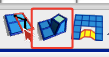
 4) Select the three faces on the pinky side of the hand and extrude them once. After you extrude but before you move the faces you'll need to click the double circle. (This changes how the extruded faces move - it makes them move in world space instead of local space.) Then move them straight out toward the pinky.
 5) Move the vertices closest to the base of the hand up so there starts to be some shape on the pinky side of the hand. Then select the face that is still straight and extrude and move it out twice.
 6) Now delete the faces in between the vertices you moved up and the faces you extruded out.
 7) Move the bottom vertices from the newly extruded section so they're almost on top of the vertices you moved up. Then use the Merge Edge (found in menu Edit Mesh --> Merge Edge Tool) tool to merge the edges together.
 8) Select the three faces on the other side of the hand. Extrude and move them out to the edge of where you want your thumb to start. (Make sure before you move that you click the double circle to move in world space.)
 9) Add four edge loops in the places shown.
 10) Then reposition the vertices in top view so that they look like this.
Tip: When moving vertices in the top view make sure to drag over the vertices to select rather than clicking on specific ones. This allows you to select all the vertices from the top to bottom of the hand.
Thursday, May 6, 2010
Extrude Tool Tutorial
Begin by creating a polygon plane.


Change to edge mode. (F10)
Use the extrude tool  ,
,
and move the extruded edge perpendicularly away from the face by click dragging the arrow pointing away from the edge.

Repeat using the extrude tool on each of the sides of the plane. You can repeat the last tool used by pressing the ‘Y’ key.

Use the polygon plane and the extrude tool to create this shape.

By following the same initial setup, we can create an extrusion that creates a complete edge loop.
Rather than selecting only one edge to extrude, select all four sides and use the extrude tool.

Scale the extrusion by click dragging on the boxes instead of the arrows.

Subscribe to:
Posts (Atom)

